Talk:Lathe: Difference between revisions
Snowdenator (talk | contribs) m Snowdenator moved page Talk:Workshop/Lathe to Talk:Lathe: Tidying up |
|||
| (17 intermediate revisions by 3 users not shown) | |||
| Line 1: | Line 1: | ||
[[File:SphereLathe.jpg|300px|thumb|right|Sphere lathe with 3 jaw chuck]] | [[File:SphereLathe.jpg|300px|thumb|right|Sphere lathe with 3 jaw chuck]] | ||
''Prototyping the new lathe page before it is good for widespread use. - Aidan'' | ''Prototyping the new lathe page before it is good for widespread use. Suggestions welcome. The idea is to make the general operation of the machine more accessible to new users. - Aidan'' | ||
== The Basics == | == The Basics == | ||
We have a Sphere lathe - the design of which is based on | We have a 6" Sphere lathe - the design of which is based on a 6" Atlas - with a 0.5 hp motor. | ||
Our lathe is suitable for turning metals and plastics. Aluminium, brass, copper, delrin/acetal and nylon shouldn't present any problems. It should be possible to machine mild steel too, though you may find some additional cooling is necessary. | |||
Both the carriage and cross slide can be power-fed using the appropriate change gears and the feed-direction gearbox on the left-hand side. | |||
We are currently lacking a full set of change gears and a threading dial. | |||
== Safety == | == Safety == | ||
* Long hair '''MUST''' be tied up, long sleeves should be rolled up securely | * Long hair '''MUST''' be tied up, long sleeves should be rolled up securely. | ||
* Eye protection | * Eye protection '''MUST''' be worn. Safety glasses are in the "Safety Equipment" box. | ||
* | * The chuck key '''MUST''' be removed from the chuck before the lathe is turned on. | ||
* Gloves '''MUST NOT''' be used whilst the machine is on - if you are concerned about grease and oil use barrier cream. | |||
* The emergency stop button is located below the "Start" button. | |||
* Ensure the work is securely fixed in the chuck. | * Ensure the work is securely fixed in the chuck. | ||
* Keep the change-gear door shut whilst the machine is on. | * Keep the change-gear door shut whilst the machine is on. | ||
* Swarf is ' | * Swarf is sharp, keep an eye on it. Don't let it build up into birds-nest piles underneath the chuck. | ||
* | * Use a centre drill on work before using a normal drill. The bit will wander and could break if you don't. | ||
* Don't | * Don't change the lead screw gearbox position whilst the machine is running. | ||
* Go and check you removed the chuck key again. | * Go and check you removed the chuck key again. | ||
== Maintenance & Care == | |||
=== Oiling === | |||
The lathe must be oiled before each use. Without oil the bearings will run dry and ruin themselves and the ways will wear and become scored and inaccurate. | |||
Refer to the oiling chart (TODO: Create oiling chart) which is both here and beside the machine before use. If you aren't sure, ask. | |||
The oil currently used is "Machine & Slideway Oil". If the bottle runs out let someone know so it can be replaced. | |||
=== Tapers === | |||
The spindle taper (MT3), tailstock taper (MT2) and any tooling which fits into them must be free of oil, rust, dirt and grease to lock correctly and securely. Give tooling a wipe down with '''clean''' tissue before inserting it into the taper hole to prevent damage. | |||
=== Sanding & Grinding === | |||
If you are sanding on the lathe make sure that you cover the ways with cloth or paper and clean up comprehensively when you are done - including the chuck. Magnets are available to securely hold protective material down so it won't be blown into the chuck. | |||
This is very important: the dust generated by sanding and grinding is very abrasive and will wear the ways quickly, turning the precision machinery we have at the moment into a sloppy, inaccurate pile of scrap metal. | |||
== Tools == | == Tools == | ||
We currently have: | We currently have: | ||
*A selection of carbide tipped tools | * A selection of carbide tipped tools | ||
* | * 2 x 13mm drill chucks and a live centre for the tailstock | ||
* | * Centre drills | ||
*Knurling tool | * Knurling tool | ||
* 4-Jaw Independent Chuck | |||
* 3-Jaw Self-Centring Chuck | |||
* 6-inch Faceplate | |||
We'd like: | We'd like: | ||
*A full set of change-gears | *A full set of change-gears | ||
*Quick change tool post ( | *Quick change tool post | ||
== Back Gears == | |||
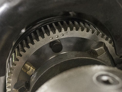
[[File:bull-gear-locating-pin.jpg|250px|thumb|right|The locating pin is on the front of the bull gear. It is black and in the centre of this image.]] | |||
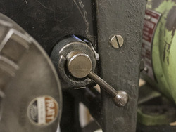
[[File:back-gear-lever.jpg|250px|thumb|right|The lever in this position is disengaged. Rotate towards the spindle to engage the back gears.]] | |||
Running the lathe using the back gears allows slow spindle speeds for threading and turning large diameters. | |||
There are two steps to setting back gear mode - the lever on the ''right hand side'' of the headstock and the plunger on the bull gear ''inside'' the headstock. | |||
* You '''MUST NOT''' attempt to run the lathe with the plunger "in" and the back gear lever engaged. | |||
* There are particular oil points that must be attended to when using the back gears. | |||
=== Engaging the back gear === | |||
* Loosen the drive belts. | |||
* Open the top of the headstock and rotate the spindle by hand until the plunger is visible. | |||
* Pull the plunger out. You might find it easier to use a small flat blade screw driver to gently lever it out. | |||
* Pull the back gear lever towards the headstock to enable the back gearing. You might need to rotate the spindle by hand slightly to allow the gears to mesh. | |||
* Turn the spindle by hand to ensure that nothing is binding. | |||
=== Disengaging the back gear === | |||
It's polite to leave the spindle in direct drive mode when you are finished with the lathe. | |||
* Push the back gear lever away from the headstock to disable the back gearing. | |||
* Open the top of the headstock and rotate the spindle by hand until the plunger is visible. | |||
* Gently push the plunger and use the belts drive system to rotate the pulleys until the plunger locates itself in its hole. | |||
== The Lead Screw == | |||
[[File:sphere-lathe-leadscrew-gearbox.jpg|250px|thumb|right|Leadscrew gearbox controls]] | |||
Power to the (8 TPI) lead screw is controlled by a small gearbox to the left hand side of the lathe. There are three positions the lever can be in: | |||
* '''Left:''' Carriage moves ''towards'' headstock, cross slide moves outwards. | |||
* '''Middle:''' Neutral. The lead screw will not turn. | |||
* '''Right:''' Carriage moves ''away'' from headstock, cross slide moves inwards. | |||
When you are not using the lead screw, put it into neutral. Ensure that each position is selected definitively using the detents in the gearbox casting otherwise you may find the lead screw stops turning partway through a cut. | |||
If you find that you can't move one of the axes of the machine check that the relevant power feed lever hasn't been engaged. | |||
Do not change lead screw direction whilst the machine is in motion. Don't engage both feeds at the same time. | |||
=== Carriage feed === | |||
[[File:sphere-lathe-apron.jpg|250px|thumb|right|Apron controls]] | |||
Carriage motion (along the bed, left and right) is controlled by the half-nut lever on the right hand side of the carriage apron. | |||
* To engage the half-nuts rotate the half-nut lever approximately 90 degrees clockwise | |||
* To disengage to the reverse. | |||
=== Cross slide feed === | |||
Cross slide feed is useful on long facing cuts and, if you are brave, when parting off. | |||
* Pull out the plunger underneath the cross slide handle to engage cross-feed. | |||
* Push the plunger in again to disengage the cross feed. | |||
== Selecting a spindle speed == | == Selecting a spindle speed == | ||
[[File:spindle-speeds-belts.png|250px|thumb|right|Belt position diagram]] | [[File:spindle-speeds-belts.png|250px|thumb|right|Belt position diagram]] | ||
The motor runs at | The motor runs at 1420 RPM and there are two belts you can change to select a spindle speed. The belt from the motor to the countershaft has two positions and the belt from the countershaft to the spindle has four. | ||
For general turning you should refer to a suitable machinist's book (or [http://its.fvtc.edu/machshop2/speeds/rpmcalc.htm the internet]) to find an appropriate spindle speed. As a general rule, the harder the material you are turning the slower the cutting speed. | |||
The belts must be run straight from one set of pulleys to another and not offset. | |||
All speeds below are in RPM. [http://scottandersonpipes.com/atlas_press/tb_6lube.htm Source] | |||
{| class="wikitable" | {| class="wikitable" | ||
! colspan="3" style="text-align: center; font-weight: bold;" | Direct Drive | ! colspan="3" style="text-align: center; font-weight: bold;" | Direct Drive | ||
|- | |- | ||
! rowspan="2" style="text-align: center; font-weight: bold;" | Spindle Belt | |||
! colspan="2" style="text-align: center; font-weight: bold;" | Motor Belt | |||
|- | |- | ||
! style="text-align: center; font-weight: bold;" | A | |||
! style="text-align: center; font-weight: bold;" | B | |||
|- | |- | ||
! style="text-align: center; font-weight: bold;" | 1 | |||
| style="text-align: center;" | 380 | | style="text-align: center;" | 380 | ||
| style="text-align: center;" | 975 | | style="text-align: center;" | 975 | ||
|- | |- | ||
! style="text-align: center; font-weight: bold;" | 2 | |||
| style="text-align: center;" | 540 | | style="text-align: center;" | 540 | ||
| style="text-align: center;" | 1380 | | style="text-align: center;" | 1380 | ||
|- | |- | ||
! style="text-align: center; font-weight: bold;" | 3 | |||
| style="text-align: center;" | 835 | | style="text-align: center;" | 835 | ||
| style="text-align: center;" | 2150 | | style="text-align: center;" | 2150 | ||
|- | |- | ||
! style="text-align: center; font-weight: bold;" | 4 | |||
| style="text-align: center;" | 2285 | | style="text-align: center;" | 2285 | ||
| style="text-align: center;" | 3050 | | style="text-align: center;" | 3050 | ||
| Line 75: | Line 160: | ||
! colspan="3" style="text-align: center; font-weight: bold;" | Back Gear | ! colspan="3" style="text-align: center; font-weight: bold;" | Back Gear | ||
|- | |- | ||
! rowspan="2" style="font-weight: bold;" | Spindle Belt | |||
! colspan="2" style="text-align: center; font-weight: bold;" | Motor Belt | |||
|- | |- | ||
! style="text-align: center; font-weight: bold;" | A | |||
! style="text-align: center; font-weight: bold;" | B | |||
|- | |- | ||
! style="text-align: center; font-weight: bold;" | 1 | |||
| style="text-align: center;" | 55 | | style="text-align: center;" | 55 | ||
| style="text-align: center;" | 145 | | style="text-align: center;" | 145 | ||
|- | |- | ||
! style="text-align: center; font-weight: bold;" | 2 | |||
| style="text-align: center;" | 82 | | style="text-align: center;" | 82 | ||
| style="text-align: center;" | 310 | | style="text-align: center;" | 310 | ||
|- | |- | ||
! style="text-align: center; font-weight: bold;" | 3 | |||
| style="text-align: center;" | 125 | | style="text-align: center;" | 125 | ||
| style="text-align: center;" | 415 | | style="text-align: center;" | 415 | ||
|- | |- | ||
! style="text-align: center; font-weight: bold;" | 4 | |||
| style="text-align: center;" | 185 | | style="text-align: center;" | 185 | ||
| style="text-align: center;" | 463 | | style="text-align: center;" | 463 | ||
|} | |} | ||
== Work-holding == | |||
There are a variety of ways to hold work to be turned in the lathe. At the Hackspace we have a 3-jaw and a 4-jaw chuck available for use. | |||
The spindle nose is threaded (8 TPI, 1.5" major diameter thread) and should be cleaned every time the chuck is changed. Similarly, the female chuck thread should be cleaned before each use. | |||
Don't assume the previous user has cleaned it well enough! | |||
When threading the chuck onto the spindle nose do so gently but firmly - there is no need to 'snap' the chuck onto the last section of the thread. When unscrewing the chuck from the spindle do so carefully: it will come off the last thread very suddenly and you could drop it onto the ways. This has already happened a few times in this lathe's history (there are a few dents on the ways under the spindle) but it would be great if it didn't happen again! | |||
Spin the chuck by hand before you turn the power on to check that nothing will collide at high speed and of course always, always ensure that the chuck key has been removed to prevent injury to yourself or other people and (most importantly) damage to the machine. | |||
=== 3-Jaw Chuck === | |||
The 3-jaw is the easiest to use, but it's also pretty inaccurate and will only get more inaccurate over time. | |||
If you ever take the chuck apart for cleaning keep in mind that the jaws are numbered (1, 2 and 3) and they each fit into their respective slots in the body and must be inserted onto the scroll in that order. If you don't they won't meet in the centre and you'll have to start from scratch! | |||
=== 4-Jaw Chuck === | |||
If you are working with a part which has already been machined (or you haven't got much spare material, diameter wise) it's important to get the work running as 'true' as possible. | |||
The 4-jaw independent chuck can, with a bit of effort, be fine tuned to hold the work very concentrically. For more information see [http://www.youtube.com/watch?v=npJfKhkS0QE this short (3 min) video]. There are two chuck keys for the 4-jaw. | |||
If you want to deliberately off-set the work to turn an eccentric feature this is also very easy with the four-jaw. | |||
=== Faceplate === | |||
A faceplate allows you to turn oddly shaped work and to give reliable drive power to work being turned between centres using a lathe dog. | |||
== Useful References == | |||
* [http://www.youtube.com/watch?v=B5pjWkJ9ewU The Bible of Metal-Working with a Lathe] | |||
* [http://www.youtube.com/watch?v=sQRfBHUqQs4 Plain Turning on the Metal Working Lathe] | |||
* [http://www.youtube.com/watch?v=oLT2GEzOWO0 How to machine a shaft at two different diameters] | |||
* [http://www.youtube.com/watch?v=a3YpkCYKY00 How to Shape Lathe Cutting Tools (also covers tool height adjustment)] | |||
* [http://www.youtube.com/watch?v=90EuSPWkLrY How to Cut a Fine Thread on a Lathe] | |||
* [http://www.youtube.com/channel/UCKLIIdKEpjAnn8E76KP7sQg Tubalcain channel - The Machine Shop Tips series is really useful] | |||
== Parts == | |||
gibbs set screws: | |||
3/16th dog point x + Nut | |||
Latest revision as of 09:44, 14 September 2016
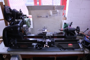
Prototyping the new lathe page before it is good for widespread use. Suggestions welcome. The idea is to make the general operation of the machine more accessible to new users. - Aidan
The Basics
We have a 6" Sphere lathe - the design of which is based on a 6" Atlas - with a 0.5 hp motor.
Our lathe is suitable for turning metals and plastics. Aluminium, brass, copper, delrin/acetal and nylon shouldn't present any problems. It should be possible to machine mild steel too, though you may find some additional cooling is necessary.
Both the carriage and cross slide can be power-fed using the appropriate change gears and the feed-direction gearbox on the left-hand side.
We are currently lacking a full set of change gears and a threading dial.
Safety
- Long hair MUST be tied up, long sleeves should be rolled up securely.
- Eye protection MUST be worn. Safety glasses are in the "Safety Equipment" box.
- The chuck key MUST be removed from the chuck before the lathe is turned on.
- Gloves MUST NOT be used whilst the machine is on - if you are concerned about grease and oil use barrier cream.
- The emergency stop button is located below the "Start" button.
- Ensure the work is securely fixed in the chuck.
- Keep the change-gear door shut whilst the machine is on.
- Swarf is sharp, keep an eye on it. Don't let it build up into birds-nest piles underneath the chuck.
- Use a centre drill on work before using a normal drill. The bit will wander and could break if you don't.
- Don't change the lead screw gearbox position whilst the machine is running.
- Go and check you removed the chuck key again.
Maintenance & Care
Oiling
The lathe must be oiled before each use. Without oil the bearings will run dry and ruin themselves and the ways will wear and become scored and inaccurate.
Refer to the oiling chart (TODO: Create oiling chart) which is both here and beside the machine before use. If you aren't sure, ask.
The oil currently used is "Machine & Slideway Oil". If the bottle runs out let someone know so it can be replaced.
Tapers
The spindle taper (MT3), tailstock taper (MT2) and any tooling which fits into them must be free of oil, rust, dirt and grease to lock correctly and securely. Give tooling a wipe down with clean tissue before inserting it into the taper hole to prevent damage.
Sanding & Grinding
If you are sanding on the lathe make sure that you cover the ways with cloth or paper and clean up comprehensively when you are done - including the chuck. Magnets are available to securely hold protective material down so it won't be blown into the chuck.
This is very important: the dust generated by sanding and grinding is very abrasive and will wear the ways quickly, turning the precision machinery we have at the moment into a sloppy, inaccurate pile of scrap metal.
Tools
We currently have:
- A selection of carbide tipped tools
- 2 x 13mm drill chucks and a live centre for the tailstock
- Centre drills
- Knurling tool
- 4-Jaw Independent Chuck
- 3-Jaw Self-Centring Chuck
- 6-inch Faceplate
We'd like:
- A full set of change-gears
- Quick change tool post
Back Gears
Running the lathe using the back gears allows slow spindle speeds for threading and turning large diameters.
There are two steps to setting back gear mode - the lever on the right hand side of the headstock and the plunger on the bull gear inside the headstock.
- You MUST NOT attempt to run the lathe with the plunger "in" and the back gear lever engaged.
- There are particular oil points that must be attended to when using the back gears.
Engaging the back gear
- Loosen the drive belts.
- Open the top of the headstock and rotate the spindle by hand until the plunger is visible.
- Pull the plunger out. You might find it easier to use a small flat blade screw driver to gently lever it out.
- Pull the back gear lever towards the headstock to enable the back gearing. You might need to rotate the spindle by hand slightly to allow the gears to mesh.
- Turn the spindle by hand to ensure that nothing is binding.
Disengaging the back gear
It's polite to leave the spindle in direct drive mode when you are finished with the lathe.
- Push the back gear lever away from the headstock to disable the back gearing.
- Open the top of the headstock and rotate the spindle by hand until the plunger is visible.
- Gently push the plunger and use the belts drive system to rotate the pulleys until the plunger locates itself in its hole.
The Lead Screw
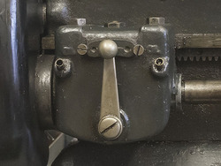
Power to the (8 TPI) lead screw is controlled by a small gearbox to the left hand side of the lathe. There are three positions the lever can be in:
- Left: Carriage moves towards headstock, cross slide moves outwards.
- Middle: Neutral. The lead screw will not turn.
- Right: Carriage moves away from headstock, cross slide moves inwards.
When you are not using the lead screw, put it into neutral. Ensure that each position is selected definitively using the detents in the gearbox casting otherwise you may find the lead screw stops turning partway through a cut.
If you find that you can't move one of the axes of the machine check that the relevant power feed lever hasn't been engaged.
Do not change lead screw direction whilst the machine is in motion. Don't engage both feeds at the same time.
Carriage feed
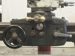
Carriage motion (along the bed, left and right) is controlled by the half-nut lever on the right hand side of the carriage apron.
- To engage the half-nuts rotate the half-nut lever approximately 90 degrees clockwise
- To disengage to the reverse.
Cross slide feed
Cross slide feed is useful on long facing cuts and, if you are brave, when parting off.
- Pull out the plunger underneath the cross slide handle to engage cross-feed.
- Push the plunger in again to disengage the cross feed.
Selecting a spindle speed
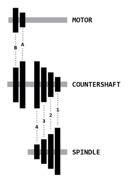
The motor runs at 1420 RPM and there are two belts you can change to select a spindle speed. The belt from the motor to the countershaft has two positions and the belt from the countershaft to the spindle has four.
For general turning you should refer to a suitable machinist's book (or the internet) to find an appropriate spindle speed. As a general rule, the harder the material you are turning the slower the cutting speed.
The belts must be run straight from one set of pulleys to another and not offset.
All speeds below are in RPM. Source
| Direct Drive | ||
|---|---|---|
| Spindle Belt | Motor Belt | |
| A | B | |
| 1 | 380 | 975 |
| 2 | 540 | 1380 |
| 3 | 835 | 2150 |
| 4 | 2285 | 3050 |
By enabling the back gear function the speed of the spindle can be reduced (and thus the torque increased) to a speed useful for threading, turning large diameter pieces and parting off.
| Back Gear | ||
|---|---|---|
| Spindle Belt | Motor Belt | |
| A | B | |
| 1 | 55 | 145 |
| 2 | 82 | 310 |
| 3 | 125 | 415 |
| 4 | 185 | 463 |
Work-holding
There are a variety of ways to hold work to be turned in the lathe. At the Hackspace we have a 3-jaw and a 4-jaw chuck available for use.
The spindle nose is threaded (8 TPI, 1.5" major diameter thread) and should be cleaned every time the chuck is changed. Similarly, the female chuck thread should be cleaned before each use.
Don't assume the previous user has cleaned it well enough!
When threading the chuck onto the spindle nose do so gently but firmly - there is no need to 'snap' the chuck onto the last section of the thread. When unscrewing the chuck from the spindle do so carefully: it will come off the last thread very suddenly and you could drop it onto the ways. This has already happened a few times in this lathe's history (there are a few dents on the ways under the spindle) but it would be great if it didn't happen again!
Spin the chuck by hand before you turn the power on to check that nothing will collide at high speed and of course always, always ensure that the chuck key has been removed to prevent injury to yourself or other people and (most importantly) damage to the machine.
3-Jaw Chuck
The 3-jaw is the easiest to use, but it's also pretty inaccurate and will only get more inaccurate over time.
If you ever take the chuck apart for cleaning keep in mind that the jaws are numbered (1, 2 and 3) and they each fit into their respective slots in the body and must be inserted onto the scroll in that order. If you don't they won't meet in the centre and you'll have to start from scratch!
4-Jaw Chuck
If you are working with a part which has already been machined (or you haven't got much spare material, diameter wise) it's important to get the work running as 'true' as possible.
The 4-jaw independent chuck can, with a bit of effort, be fine tuned to hold the work very concentrically. For more information see this short (3 min) video. There are two chuck keys for the 4-jaw.
If you want to deliberately off-set the work to turn an eccentric feature this is also very easy with the four-jaw.
Faceplate
A faceplate allows you to turn oddly shaped work and to give reliable drive power to work being turned between centres using a lathe dog.
Useful References
- The Bible of Metal-Working with a Lathe
- Plain Turning on the Metal Working Lathe
- How to machine a shaft at two different diameters
- How to Shape Lathe Cutting Tools (also covers tool height adjustment)
- How to Cut a Fine Thread on a Lathe
- Tubalcain channel - The Machine Shop Tips series is really useful
Parts
gibbs set screws: 3/16th dog point x + Nut