CNC Mill Guide: Difference between revisions
No edit summary |
No edit summary |
||
| (14 intermediate revisions by 2 users not shown) | |||
| Line 1: | Line 1: | ||
[[File:Metalshop_guy.jpeg|thumb|alt=Typical presentation of the symptoms associated with CNC Mill over use. |Typical presentation of the symptoms associated with CNC Mill over use. . ''[[CNC Mill]]''.]] | [[File:Metalshop_guy.jpeg|thumb|alt=Typical presentation of the symptoms associated with CNC Mill over use. |Typical presentation of the symptoms associated with CNC Mill over use. . ''[[CNC Mill]]''.]] | ||
=Welcome= | =Welcome= | ||
Welcome to the CNC Mill Guide, this is a reference body of information with the aim to introduce you to the CNC Mill. Like most workshop tasks having a job go easily and ending with quality is a result of experience. The machine will only do what you tell it. Acquiring ninja-master of milling almost always requires purchase of a apron one way or another. | Welcome to the CNC Mill Guide, this is a reference body of information with the aim to introduce you to the [[CNC Mill]]. Like most workshop tasks having a job go easily and ending with quality is a result of experience. The machine will only do what you tell it. Acquiring ninja-master of milling almost always requires purchase of a apron one way or another. | ||
=Know | =Know the machine= | ||
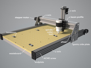
Get to know the bits on the machine and what they are called, eventually you might need to show someone else. Specifications of the machine | Get to know the bits on the machine and what they are called, eventually you might need to show someone else. Specifications of the mill are as follows: | ||
*800W spindle | |||
*ER11 collet | |||
*355x250x50mm machine workspace | |||
*6000-24000 RPM | |||
[[File:cncmilldia. | [[File:cncmilldia.jpg|thumb|alt=CNC Mill Diagram.|CNC Mill Diagram.''[[CNC Mill]]''.]] | ||
= | =Workflow= | ||
A brief but complete overview of running a job from beginning to end. All workflows share a few essential steps: CAD -> CAM -> Gcode -> Machine. | A brief but complete overview of running a job from beginning to end. All workflows share a few essential steps: CAD -> CAM -> Gcode -> Machine. | ||
==Design the part== | ==1. Design the part== | ||
CNC design requires that one draw or code the part(s) up on a computer, either in a CAD program, or directly in a CAM program which has drawing facilities, or directly in G-Code. See [Designing for Fabrication] for further considerations. | CNC design requires that one draw or code the part(s) up on a computer, either in a CAD program, or directly in a CAM program which has drawing facilities, or directly in G-Code. See [Designing for Fabrication] for further considerations. | ||
| Line 18: | Line 22: | ||
*Basic workflow 2D --- drawing a part in Inkscape, creating toolpaths with HeeksCNC, simulating toolpaths with OpenSCAM | *Basic workflow 2D --- drawing a part in Inkscape, creating toolpaths with HeeksCNC, simulating toolpaths with OpenSCAM | ||
*Basic workflow 3D --- glosses over drawing a part, but covers using HeeksCNC to create toolpaths, simulating with OpenSCAM | *Basic workflow 3D --- glosses over drawing a part, but covers using HeeksCNC to create toolpaths, simulating with OpenSCAM | ||
* | *BHSPitMonkey's Inkscape and Gcodetools Tutorial --- detailed, illustrated tutorial | ||
*Tutorial CAD/CAM 3D Diamond-Circle-Square InkScape/MakerCAM --- drawing parts in Inkscape, setting up paths w/ MakerCAM | *Tutorial CAD/CAM 3D Diamond-Circle-Square InkScape/MakerCAM --- drawing parts in Inkscape, setting up paths w/ MakerCAM | ||
*Cutting Embossed name plate --- There is a video tutorial for this on the MakerCAM page | *Cutting Embossed name plate --- There is a video tutorial for this on the MakerCAM page | ||
| Line 25: | Line 29: | ||
Video Tutorials | Video Tutorials | ||
CAD | CAD | ||
*ShapeOko 2 Project: Gear Coaster | *ShapeOko 2 Project: Gear Coaster | ||
*Sparkfun: ShapeOko—Make a Coaster | *Sparkfun: ShapeOko—Make a Coaster | ||
PCB Milling | PCB Milling | ||
*How to mill a PCB with Chilipeppr + GRBL (2 episodes) by Frank Herrman | *How to mill a PCB with Chilipeppr + GRBL (2 episodes) by Frank Herrman | ||
==2. CAM / Generate G-Code== | |||
Sanity checking G-Code is always advised, checking a external profile cut for tabs is a must! | |||
==3. Prepare for cut== | |||
Hold down the work in a sensible way, pick the correct tooling. | |||
==4. Operate the mill== | |||
Home the machine, zero the work piece, test mode your code. Cut your code! | |||
=The Induction= | |||
Using a CNC Mill requires a bit more background knowledge or learning than a laser cutter or 3d printer. The induction is aimed at working with that knowledge on our CNC. | |||
==Before the induction== | |||
You should come to the session having some knowledge of CAD and CAM concepts and have used a CAD/CAM package such as Autodesk Fusion 360(free, works on Windows or OSX) or other package capable of generating g-code for CNC machining. The induction leader will be happy to help with explaining concepts but depending on your previous experience there is quite a lot to learn so you will get the most out of the session and the machine if you do some independent reading / practice. | |||
In particular before coming you should learn a bit about: | |||
*The difference between CAD geometry files (i.e. DXF, IGES and STEP), and tool path files (i.e. G-Code) | |||
*Cutting materials - cutter speeds and feed rates - dependent on what you want to cut. Some things (i.e. wax, modeling board) are very forgiving, while others (particularly metals) need to be just right for good results. | |||
*Any CAM package, Fusion 360 is a good one if you are not sure. You should try generating a tool path with a particular cutter, checking the toolpath visually and by simulation if your CAM software allows it, and finally posting the G-Code to the a g-code file (i.e. .gcode extension). | |||
*XYZ coordinate systems (on our CNC, x is left to right (+x is travelling right), y is towards / away from you (+y is gantry travelling away from you), and z is down / up (+z is travelling up) | |||
*Concept of finding datum of the workpiece, for instance touching off the tool in x, y and z (z is very important) | |||
*Checking a CAM toolpath by simulating the cut, and also checking the extents of the tool path to make sure it is not going to run into any fixtures or the bed of the machine. | |||
There is machinable wax available so you can experiment a bit after the training (highly recommended!), while there are people around to help you. | |||
Latest revision as of 14:33, 6 December 2016

Welcome
Welcome to the CNC Mill Guide, this is a reference body of information with the aim to introduce you to the CNC Mill. Like most workshop tasks having a job go easily and ending with quality is a result of experience. The machine will only do what you tell it. Acquiring ninja-master of milling almost always requires purchase of a apron one way or another.
Know the machine
Get to know the bits on the machine and what they are called, eventually you might need to show someone else. Specifications of the mill are as follows:
- 800W spindle
- ER11 collet
- 355x250x50mm machine workspace
- 6000-24000 RPM

Workflow
A brief but complete overview of running a job from beginning to end. All workflows share a few essential steps: CAD -> CAM -> Gcode -> Machine.
1. Design the part
CNC design requires that one draw or code the part(s) up on a computer, either in a CAD program, or directly in a CAM program which has drawing facilities, or directly in G-Code. See [Designing for Fabrication] for further considerations.
List of end-to-end tutorials
- Basic workflow 2D --- drawing a part in Inkscape, creating toolpaths with HeeksCNC, simulating toolpaths with OpenSCAM
- Basic workflow 3D --- glosses over drawing a part, but covers using HeeksCNC to create toolpaths, simulating with OpenSCAM
- BHSPitMonkey's Inkscape and Gcodetools Tutorial --- detailed, illustrated tutorial
- Tutorial CAD/CAM 3D Diamond-Circle-Square InkScape/MakerCAM --- drawing parts in Inkscape, setting up paths w/ MakerCAM
- Cutting Embossed name plate --- There is a video tutorial for this on the MakerCAM page
- CNCZone thread on CAM for a watch case and fixturing: http://www.cnczone.com/forums/tormach-personal-cnc-mill/128923-tormach-2.html#post955484
Video Tutorials CAD
- ShapeOko 2 Project: Gear Coaster
- Sparkfun: ShapeOko—Make a Coaster
PCB Milling
- How to mill a PCB with Chilipeppr + GRBL (2 episodes) by Frank Herrman
2. CAM / Generate G-Code
Sanity checking G-Code is always advised, checking a external profile cut for tabs is a must!
3. Prepare for cut
Hold down the work in a sensible way, pick the correct tooling.
4. Operate the mill
Home the machine, zero the work piece, test mode your code. Cut your code!
The Induction
Using a CNC Mill requires a bit more background knowledge or learning than a laser cutter or 3d printer. The induction is aimed at working with that knowledge on our CNC.
Before the induction
You should come to the session having some knowledge of CAD and CAM concepts and have used a CAD/CAM package such as Autodesk Fusion 360(free, works on Windows or OSX) or other package capable of generating g-code for CNC machining. The induction leader will be happy to help with explaining concepts but depending on your previous experience there is quite a lot to learn so you will get the most out of the session and the machine if you do some independent reading / practice.
In particular before coming you should learn a bit about:
- The difference between CAD geometry files (i.e. DXF, IGES and STEP), and tool path files (i.e. G-Code)
- Cutting materials - cutter speeds and feed rates - dependent on what you want to cut. Some things (i.e. wax, modeling board) are very forgiving, while others (particularly metals) need to be just right for good results.
- Any CAM package, Fusion 360 is a good one if you are not sure. You should try generating a tool path with a particular cutter, checking the toolpath visually and by simulation if your CAM software allows it, and finally posting the G-Code to the a g-code file (i.e. .gcode extension).
- XYZ coordinate systems (on our CNC, x is left to right (+x is travelling right), y is towards / away from you (+y is gantry travelling away from you), and z is down / up (+z is travelling up)
- Concept of finding datum of the workpiece, for instance touching off the tool in x, y and z (z is very important)
- Checking a CAM toolpath by simulating the cut, and also checking the extents of the tool path to make sure it is not going to run into any fixtures or the bed of the machine.
There is machinable wax available so you can experiment a bit after the training (highly recommended!), while there are people around to help you.