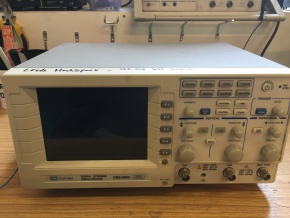
Electronics/GDS-820S
 | |
| Digital oscilloscope | |
| Equipment Information | |
|---|---|
| Status | Unknown |
| Manufacturer | GW Instek |
| Model | GDS-820S |
| Hackspace Information | |
| Induction Required | Yes |
| Induction Information | Here |
| Card RFID Enabled | No |
| Owner | Hackspace & Fligg |
The Basics
An oscilloscope is a piece of electrical test equipment which allows you to visually see an electrical signal shown on a display.
The GW Instek GDS-820S currently has an issue with triggering.
Specification
- GW Instek GDS-820S
- Digital storage oscilloscope (DSO)
- 2 channel
- Real Time sample rate: 100MS/s maximum on each channel
- Equivalent Time sample rate: 25GS/s E.T. maximum on each channel
- Bandwidth: 150MHz effectively an equivalent time bandwidth. So not strictly speaking an 150MHz scope unless you are talking about the equivalent time sample rate on a repetitive signal.
- 5.7 inch mono LCD (320x240)
- FFT, 125k/CH
- RS232, USB and GPIB
- Trigger DC-30MHz for 0.5div or 5mV, 30MHz to 150MHz 1.5 div or 15mV
- Issues: Boots now, but waveform trigger doesn't appear to be working correctly. waveforms continuously roll.
- Previous issues: Power board was repaired previously. The firmware was reflashed on two seperate occasions.
- Manual: TBD
Power on
Switch power on at the rear of the oscilloscope. Press the standby button in the top right of the front panel. Note that the button sometimes sticks.
Re-flashing
The oscilloscope has required re-flashing several times. If after pressing the standby button the LCD lights up but does not boot after you waited for more than 20 seconds, then its likely the oscilloscope has experienced this issue again.
Re-Flashing firmware procedure:
- Requires a windows machine. Works on XP, not tested on other machines.
- USB-to-serial adapter.
- Serial 9 pin cross-over cable (e.g. the blue serial cable with 2 x female 9 pin D types)
- Turn off the oscilloscope at the rear panel switch
- Connect the USB-to-serial adapter to the serial crossover cable
- Connect the serial cable to the oscilloscope
- Connect the USB-to-serial adapter to the PC. You may have to wait for drivers to install.
- Find which com port is being used in the windows control panel | system | hardware | Lpt and com option
- Download firmware for the 820S from the Instek website. This is located in the 'Discontinued' section, under the GDS-800 series download tab. Ensure you download the correct software. There will be a version for other oscilloscopes in the same area.
- Unzip the instruction pdf file and exe program which performs the update.
At this point you can either follow the Instek manual or these instructions.
- Ensure the oscilloscope is turned off
- Run the .exe
- Choose which com port you are using
- Click 'YES' to start the software
- Turn on the oscilloscope at the rear and also press the front panel standby button.
- You will need to do this in quick succession. To avoid a timeout.
- At this point a download should commence.
- If not a timeout will occur and you will be asked to power off the oscilloscope and you will have to retry.
- This may take several attempts before a download commences.
- When download is completed, you will be asked to click next to program the software. Click next (doing a little jig is encouraged at this point).
- After about 10 seconds you should then see the normal oscilloscope display
- When the oscilloscope displays the normal oscilloscope screen. Press 'Exit' on the PC programming software
- Test that the oscilloscope reboots by taking the oscilloscope into and out of standby a few times
Calibration
The spaces oscilloscopes will NOT normally have a calibration certificate. Most will be well outside their calibration date. Having said that it is common practice to perform a basic oscilloscopes calibration check before each use against a known calibration source to confirm it is suitable for use. Most oscilloscopes have a calibration signal output point on the front panel. Some have rear panel outputs.
Induction
Ask on the mailing list for volunteers to demonstrate the use of any of the test equipment.
Safety
You must read the safety documentation in this link before using this equipment.