CNC Router: Difference between revisions
| Line 32: | Line 32: | ||
For those of you used to using Fusion 360, Sketch-up or some other CAD software please use the drawings provided (coming soon) to create your G-code. | For those of you used to using Fusion 360, Sketch-up or some other CAD software please use the drawings provided (coming soon) to create your G-code. | ||
* Rough stock | * Rough stock provided is approximately 120 mm x 80 mm x 12 mm | ||
* Use a 12 mm diameter straight flute end mill to face the top surface to 10 mm thick. Leave room for clamping either end (about 5 mm top and bottom). | |||
* Use a 6 mm straight flute end mill to route the circular pocket and the profile. Keep tabs on the material to keep it in place after profiling. Two top and two bottom should be good enough. | |||
* Use a 30 degree V-engraving bit to engrave the logo 0.5 mm deep. | |||
==Using the Mill== | ==Using the Mill== | ||
Revision as of 12:21, 19 January 2017

Description
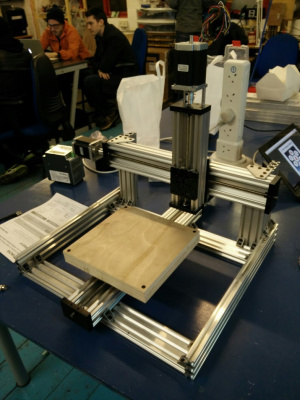
We currently have a under construction C BEAM based CNC Mill. The mill took its first cut on 20/02/2016.
The CNC Mill is based on the C BEAM profile from open builds, it is currently a X/Y table type "C BEAM MACHINE" thats 400x400x120mm but we have all the parts to make it a 1000x750mm gantry style ASAP.
To use the machine you have to be inducted, and before then you should be familar with CNC Mills (read the CNC Mill Guide); it is also a numerically controlled power tool with a variable Z and so considerable care should be taken in preparation and operation.
Please see the CNC_Mill/Feeds_and_Speeds page for information on the kind of cut settings you can use on the mill when setting up your CAM.
Once you have a valid Gcode file from your CAM package, you will be able to use http://chilipeppr.com/grbl whilst at the space to run your file on the CNC.
Specifications
- 800W water cooled spindle 220V 6.5A with ER11 collet
- 1.5kw VFD capable of 3000-23000 rpm
- 3.2Mn NEMA 23 steppers
- 36V Stepper power supply
- 2.5A Stepper drivers
- Control via GRBL running on a arduino screw terminal sheild
- Raspberry PI serial to JSON server making the CNC shield available on chillipeppr.com when at the space.
- 325x250x100mm workspace
- No load max feed of 5000mm/min
- 6 x Capacitive 6-36V end stops
Induction
You are required to undertake an induction before using this machine, which will cover the basics of workholding and running the machine. This will teach you how to set up and home the machine, change tools and run programs using the LinuxCNC software.
We will be profiling, engraving and pocketing a block of machinable wax using the G-code that you generate before the induction using the SVG file provided (coming soon). If you don't have any experience with CAD/CAM there is a YouTube video (coming soon) covering the basics of how to use the web based MakerCAM to generate suitable G-code and open-source CAMotics to verify that it is sane.
For those of you used to using Fusion 360, Sketch-up or some other CAD software please use the drawings provided (coming soon) to create your G-code.
- Rough stock provided is approximately 120 mm x 80 mm x 12 mm
- Use a 12 mm diameter straight flute end mill to face the top surface to 10 mm thick. Leave room for clamping either end (about 5 mm top and bottom).
- Use a 6 mm straight flute end mill to route the circular pocket and the profile. Keep tabs on the material to keep it in place after profiling. Two top and two bottom should be good enough.
- Use a 30 degree V-engraving bit to engrave the logo 0.5 mm deep.
Using the Mill
You need an induction before you can use this machine.
Reading this summary is not an induction, and is for reminder only.
Power-On Cycle
- Turn on the power to the control box located underneath the router bed using the switch labelled Main Power
- Turn on the controller PC. If the PC is already turned on, restart it - the control box needs to be on before the PC boots so that it can talk to the VFD correctly.
- Release all of the CNC router's Emergency Stop buttons.
- Once the PC has booted and loaded LinuxCNC click the Power button on the main interface, located in the top right.
Homing
Every time the CNC router is turned on it needs to be homed. Homing moves all three axes to a known location so that the software can keep track of where it is. You will also have to re-home the machine after you have used the emergency stop or crashed into something.
Until the machine has been homed the controller will not allow you to manually enter G-Code in MDI mode or run an NC program in Auto mode.
Homing functions are available on the home toolbar at the bottom of the screen. Click the first button to home all axes sequentially, or each of the other buttons to home an axis individually. The return button in the bottom right will take the toolbar back to the main screen.
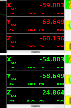
As the machine homes each axis the corresponding Digital Read Out (DRO) in the top right corner will change from red to green.
Jogging the machine
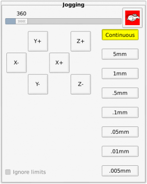
Use the jogging controls to move the machine's axes. When moving the Y axis, think of it as if you are moving the spindle instead of the table. If you think that you are moving the table the jog directions will seems a bit odd.
Clicking the hare icon will change it to a tortoise and it will put the machine into slow jogging mode - if you find that you can't jog around the table as fast as normal check that you aren't in tortoise mode. Additionally you can adjust the jog speed using the slider, the unit being millimetres per minute.
The continuous mode is most useful for zipping around the work area, but as you get closer to the work and want to zero out it's quite helpful to change to one of the smaller options. Every time you press a key or button to jog it will move in discrete increments thus allowing you to sneak up on a dimension.
Remember that the arrow keys on the keyboard also work to move in the X & Y dimensions, and Page Up and Page Down will move the Z axis. Pay particular attention when moving the Z-axis as it takes longer to move a similar distance and will often keep moving after you feel like it should have stopped.
Manual Data Input (MDI) mode
It is much easier to move a machine precise amounts using G-Code. Once the machine has been homed you can access the MDI screen and enter G-Code to position the machine quickly and precisely, or even to perform quick one-off cuts.
You need to understand basic G-code in order to use this machine, and this is the best place to check whether commands will do what you expect them to do. Be careful when entering commands, it's very easy to crash the machine.
You might like to try moving the X axis to 0 as a 'rapid' movement using G00 X0, or performing a cut movement to Y axis position 10 at a rate of 250 mm/min with G01 Y10 F250. Starting the spindle at 8000 RPM is achieved using M3 S8000 and changing the speed to 10,000 RPM is done by entering S10000. You can stop the spindle with M5. These are just examples, you really need to know basic g-code so that you can catch errors before they cause problems and ruin the machine or your work.
We've done our best to set the machine so that it can't over-travel and wreck itself, but if you really abuse it you might run into problems, especially on the Z axis.
Configuration
The LinuxCNC configuration files are stored on Github for you to browse. Please don't edit anything on the machine without checking with someone else first. If you do make a change please submit a pull request. Ask if you are not sure how.
VFD
The spindle is controlled by a Huanyang HY01D523B VFD. The current configuration settings can be found on the VFD page.
Drivers / Motors
Drivers are TB6600's 'capable' of 50V 5A
- 1/4 microstep mode
- Full power
- Supplied with 36V
Motors are 3.1Nm Nema 23
- Wired in series mode
- [Datasheet]
Build notes
The end stops are wired as follows:
1 - Positive 2 - Gnd 3 - Signal 4 - Signal
Experimentation is required to determine which detector
Pledges
A pledge tracker can be found on this google sheet [1]
Design
The first machine is a 'out of the box' C Beam Machine kit [2]. This is a X/Y table machine based on the C Beam aluminum profile which offers better stability and accuracy than OX type v slot or shapeoko.
This kit will be used to make the plates for its own upgrades into our specific 1000mm x 750mm gantry style machine with dual X drive based on this design. [3]
Parts Status
We have purchased the majority of parts from Colin at robocutters.co.uk[4], he offered a wealth of advice, a great discount and is genuinely interested in supporting Hackspaces.
- A C Beam machine kit
- 3 NEMA 23 Motors
- 1 1000mm linear actuator kit
- 1 750mm linear actuator kit
- 4 750mm 60 aluminium profiles
- 16 wheel kits
From China we ordered as a kit:
- 800W 60mm mount water cooled spindle
- 1.5kW VFD
- 12 VPump
- Various collets
From other sources:
- 6 C.P type limit switches (swwils)
- Radiator (swwils)
- 4 Core spindle cable (swwils)
- RUMBA Board + Drivers (Martyn)
- E-stop (Aidan)
- Arduino CNC sheild (swwils)
- Arduino UNO (swwils)
- 36v 10A PSU (Aidan)
Parts needed
- Cable chains (larger machine)
- Regular stop / go button
Build log
- First cut occurred
- Limit switches installed.
- Hard limits set
- Soft limits set (but broken!)
- Dir inversion issues (0,0 should be lower left?)
- Dir inversion worked out (its actually correct to set machine into negative space)
- TB6600 Stepper Drivers Installed
- Wasteboard installed
- Some hold downs installed
- Machine tightened and thread locked (blue)
Upcoming
- Writing documentation
- PWM spindle control / enable
Software Proposals
GRBL vs TINYG [5]
CAM [6]


